Temperature monitoring and control is a fundamental necessity of brewing. All-grain brewers must monitor not only mash temperature but that of the strike and sparge water as well. Extract brewers need to know when to remove specialty grains from the brew kettle to avoid leaching unpleasant flavors from the grains at high water temperatures.
There are many kinds of thermometers available to the homebrewer. Each has advantages and disadvantages in their use. Mercury or alcohol thermometers can be very accurate but are prone to breakage if mishandled and usually must be read from the side, which make them impractical for checking temperatures deep inside a vessel. Dial thermometers offer good performance and accuracy and perhaps are the homebrewer's top choice, but often the dial scales are small and hard to read. Larger dial thermometers can be expensive and harder to find.
Electronic thermometers offer a direct numerical readout and use a remote
sensing probe, which allows one to easily read temperatures in difficult-to-reach
areas. They can be home-built at low cost and rival or exceed the best
dial thermometers in accuracy. Perhaps their best feature is that they
provide a "front end" for electronic temperature controllers and other
devices.
Perhaps the best electronic sensor for our applications is a piece of silicon available in the form of a diode. A diode is an inexpensive electronic component designed to allow current to flow through it in one direction, but which blocks current attempting to flow in the opposite direction. Picture a diode as an electronic "check valve" allowing electrons (instead of fluid) to flow in one direction only. As current flows in the diode, a voltage builds across it. For a given diode, this voltage depends on two things: the amount of current flowing through it, and the diode's temperature. If we can establish a fixed and known current, we can assume that any changes in the diode voltage are due only to changes in temperature.
The change in the diode's voltage in response to temperature changes
is very linear, so we've solved a big problem there. There are a couple
of other problems though that will require addressing before we can use
a diode in a direct-reading thermometer. First, most of the voltage cross
the diode must be "subtracted" to leave only the part which changes proportionally
to the temperature units we are interested in (normally degrees F or C).
This "offset" voltage is roughly 0.5 to 0.7 volts. Next, the voltage change
in response to temperature change is very small; about 1.22 thousandths
of a volt (1.22 mV) per degree Fahrenheit (or 2.2 mV/deg C). Finally, the
voltage
drops as temperature rises, and rises as temperature
drops.
So in order to use a diode in a direct-reading thermometer, we must (1)
subtract the amount of voltage required to "leave" only the part that changes
with temperature, (2) amplify or "scale" the remaining voltage change
to match the desired readout in degrees, and (3) "invert" or "reverse"
the direction of change so that the voltage rises with rising temperature
and vice-versa. Normally we would do these three things so that 10 millivolts
of voltage equals one degree of temperature. This relationship allows direct
temperature readout on a digital voltmeter while keeping the voltage levels
reasonable.
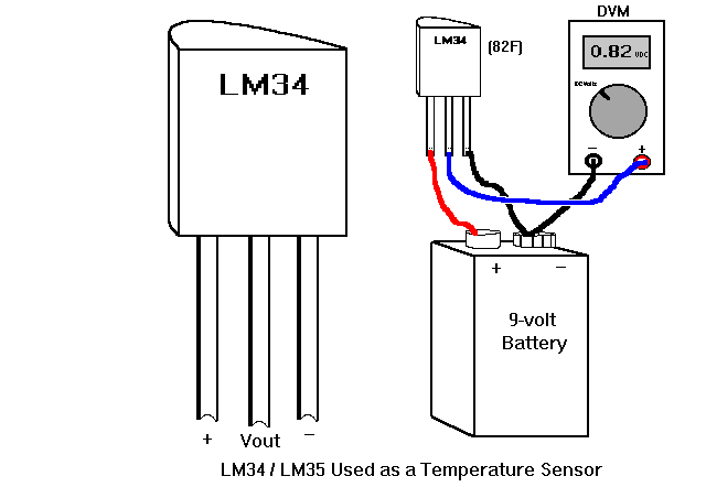
The main problem with the LM34/35 is that the most accurate versions are also the most expensive (up to $30 for the "A" grade). Less-accurate grades are available reasonably priced, but they can be off by as much as four degrees Fahrenheit ("D" grade). And since they are usually only available mail-order, you must meet minimum-order requirements or pay surcharges if you are below the minimum-order. However, for general-purpose use, they are excellent and very simple to use devices. The diagram below shows how to wire an LM34 or LM35 with a battery and DVM. Be sure all exposed wires are covered with insulating material such as heat-shrink tubing or food-grade silicone adhesive.
Another device often cited is the LM335, which is similar to the LM34
in operation but reads out in degrees Kelvin (absolute temperature).
They are often inexpensive but again their accuracy is only fair (comparable
to the lower grades of the LM34 & LM35) and must usually be mail-ordered.
Any transistor will work as a sensor, but I recommend one in the "TO-92" case style. This little "half-round" black plastic package physically lends itself well to being used as a probe tip. Radio Shack's 276-2058 (type 2N4401) is their least expensive at forty-nine cents. It's an "NPN" type, which describes it's electrical "polarity". The diagram below shows how to wire an NPN transistor as a diode. Observe the connection of the "emitter", "base" and "collector" terminals. If you use a PNP transistor, wire the transistor's terminals the same way but reverse the "+" and "-" polarity callouts. A suitable "regular" diode would be Radio Shack's #276-1122 (10 1N914-type diodes); the "striped" end is "-".
Note that transistors and diodes can be obtained in larger quantities in Radio Shack's "multi-packs". A pack of 50 1N914-type diodes (#276-1620) or 15 NPN transistors (#276-1617) can each be obtained for a bit over $2. Although these are often "experimenter grade" parts that don't always meet the manufacturers' original specifications, they are perfectly good for application as a temperature sensor. Again be sure to observe which leads correspond to "emitter", "base", and "collector", as this may vary with package style. This information is usually printed on the blister package.
Another thing to keep in mind is that every individual transistor or diode has its own particular voltage-versus-temperature characteristic. This means that if you should ever replace a probe, you must recalibrate your thermometer to "match" it to the new sensor. But as long as you always use the same sensor with the same circuit, you shouldn't need to recalibrate, although periodic checks are a good idea.


This circuit uses a nine-volt battery along with a voltage regulator IC (Radio Shack 276-1770). Remember that the diode generates a voltage which varies with both current and temperature. In order to have the diode voltage respond only to temperature, we must fix the current at a constant unchanging level. The voltage regulator provides a constant voltage, and connecting the diode to the regulator through the resistor as shown establishes a constant current through it. The exact value of the current is not important, only the fact that it doesn't change.
Astute readers may wonder how we can maintain a constant current through the diode this way, when the diode voltage is changing with temperature. Good call! However, the slight change in current due to the change in diode voltage translates to a very small additional change in the diode voltage, so the error is negligible.
After you've wired the circuit, prepare a glass of ice water and a coffee
mug with near-boiling water. Also get out your favorite, most accurate
thermometer as a reference. Tie the sensor to the reference thermometer
with a twisty and dunk them into the ice water. Allow them to settle for
a few minutes to equilibrate with the surrounding temperature. With the
thermometer and sensor still immersed, read the temperature from the reference
thermometer and the voltage from the DVM. Write these numbers down. Now
repeat using the hot water. You now have two data points. Mark them on
the graph paper and carefully draw a straight line between them. Now you
can simply read the voltage from the DVM, check the chart, and determine
the temperature with great accuracy.
In order to do this, we must solve the three "problems" discussed earlier: we must subtract a large fixed voltage, invert the direction of change of the remaining voltage, and scale or amplify its rate of change. The circuit shown below does all these things with a single section of a four-section IC amplifier chip, the LM324 (Radio Shack 276-1711). A single LM324 can thus be used as a four-channel temperature sensor simply by duplicating the circuitry shown for each of the other three sections.

Again, a voltage regulator and resistor provide a constant current through the sensor diode, generating a voltage which changes only with temperature. The diode voltage is fed to the amplifier stage, which not only amplifies it by the correct scale factor to provide 10 mV/deg output, but also inverts the "direction" of change so the voltage rises with increasing temperature. That's two of the three problems solved. The 1K pot applies a voltage to the amplifier which cancels out the "large" diode voltage that we wanted to subtract. That solves the third problem. The 330-ohm resistor helps keep the amplifier's output correct at lower temperature readings.
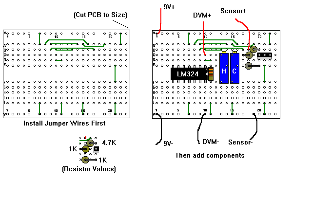
The circuit can be built on a perforated board or on a "pad-per-hole" copper-clad prototype breadboard. But I prefer to use the "modular breadboard matching PCB" sold by Radio Shack (#276-170). This pre-drilled PCB is laid out to allow easy wiring of circuits with minimal effort. It may not always produce the most elegant layout but on the other hand building circuits is easy and the finished product is as solid as a custom PCB. I have shown the wiring layout below for a single-channel unit. We will add to this board later when we look at temperature controllers, but it can be used as-is if only a thermometer is needed.
To calibrate this circuit, again prepare the cold and hot water as described above, and attach the sensor to the reference thermometer. Before we begin the actual calibration, we can make a first approximation with a rough room-temperature adjustment, which will speed the calibration process. Connect the DVM or panel meter between "ground" (the "negative" battery terminal) and the "+" input pin of the amplifier. Adjust the 1K pot so that the meter reads about 0.70V (if using Fahrenheit degrees) or 0.53V (for Celsius). Now connect the voltmeter "+" probe to the output of the amplifier (leaving the "-" probe on "ground"), and adjust the 10K to about half its rotation (7 - 8 turns from either end). This completes the "rough" calibration. Now put the sensor in the cold water, allow to equilibrate, then adjust the 1K pot ("COLD") so the voltmeter reads "the same" as the reference thermometer (i.e., if the thermometer reads "34", the voltmeter should read "0.34"). Place the sensor and thermometer into the hot water, equilibrate, and adjust the 10K pot ("HOT") so the voltmeter "matches" the thermometer ("190" degrees would read "1.90" volts). Repeat these two adjustments several times until both temperature extremes read correctly with no further adjustment. The thermometer is now calibrated. On the first set or two of measurements, it's possible that you may not be able to adjust the pots to obtain the necessary readings. Don't worry, get as close as you an and go on. Soon enough you'll have it tweaked in perfectly. If you wish, you can place a drop of glue on the pots' adjustment screws, to secure them to the pot body and prevent them from "drifting" out of position, though this shouldn't be a problem in normal use.
The thermometer will maintain its accuracy as long as the diode current
doesn't change. The voltage regulator will maintain a constant output voltage
as long as the battery voltage is above about seven volts. Check the battery
occasionally to be sure it's at seven volts or more, or you could use a
9-volt "battery eliminator" AC-adapter.
To understand this, let's take a closer look at the amplifier. It has two inputs, labeled "+" and "-". The amplifier amplifies or multiplies the difference in voltage between these two inputs. The multiplication factor or "gain" is very high, so it only takes a small difference to generate a large voltage. Typically a difference of only a few millivolts will drive the output to its limit.
We can take advantage of this fact by applying a steady "reference voltage" to the "+" input and the changing measurement or "temperature voltage" (10 mV/deg from the thermometer) to the "-" input. If the temperature voltage is higher (more positive) than the reference voltage, the amplifier's output will go as high as it can (about 1.5 volts below the supply voltage). Once the temperature voltage drops below the reference voltage, the amplifier's output goes as low as possible (zero volts). Only in a very small range of temperature will the amplifier's output be anything except "full on" or "full off", and we will deal with that too.
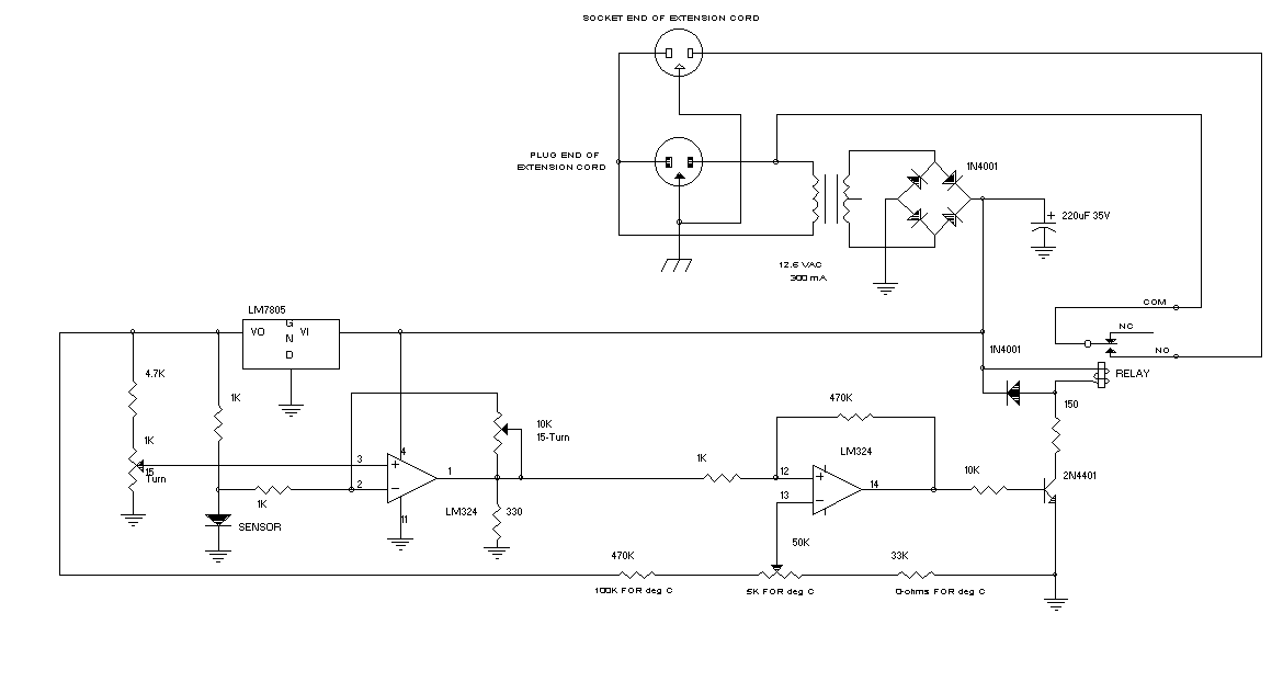
If we obtain a reference voltage from a linear-taper pot set up to supply a voltage from 0.30 volts to 0.75 volts, we can establish a setpoint temperature of 30 to 75 degrees F. Now, if the temperature in the fridge is above the setpoint, the amplifier's output goes "high". If we use that "high" voltage to activate a relay which turns the compressor on and off, the compressor will turn on when the temperature is warm compared to the setpoint, and will turn off when the temperature has fallen to the setpoint.
If we feed a bit of the output voltage back to the input, we can add some "differential" or "hysteresis" to the control. When the amplifier's output is "high", the feedback resistor pulls the temperature voltage input up just a bit, so it "thinks" that the temperature is a bit warmer than it actually is. When this "pulled-up" temperature voltage drops below the setpoint, the amplifier output goes "low". This pulls the temperature voltage down just a bit, reinforcing, if you will, the decision to turn the compressor off. In other words, the amplifier now thinks it's even colder than when it shut off the compressor. So the refrigerator temperature must rise a couple degrees before the compressor will again be switched on.
By doing this, not only is the amplifier always in a solid, secure "state of comparison", the refrigerator temperature must rise enough to overcome this "differential", and so the compressor will cycle much less frequently as a result. With the component values shown, the differential will be about 3 degrees F (about 1.5 degrees C). Changing the 470K resistor to 330K gives about 4 degrees differential.
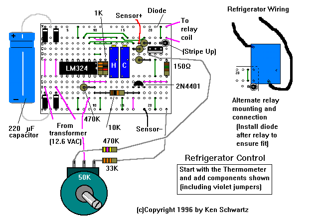
The transistor is required to ensure that the relay gets enough current to activate. The relay is a subminiature 10 amp unit that should operate all but the biggest refrigerators (Radio Shack 275-248 -- 275-217 will also work if you delete (bypass) the 150 ohm resistor). But check your refrigerator to be sure. If no current rating is given, but a power consumption rating is, you can deduce the current by dividing the power consumption by 120 (for 120V mains). This results in a 1200W maximum for the fridge (1.6 HP). The 150 ohm resistor drops the 16-volt power supply closer to the relay's rated 12 volts. You can replace this with a 100-ohm resistor and an LED; the LED will turn ON when the fridge is powered.
The power supply is now a line-operated transformer-based supply. It is unregulated and will produce about 16 volts to supply the circuit and relay. The transformer (Radio Shack 273-1385) is wired into the power cord. You can use a 16-gauge extension cord; cut off the desired length for both the plug end and the socket end, so you can reach both the wall socket and the refrigerator. Feed the green ground wire from the plug to the socket. If you are using a metal box, connect it also to the box with a screw for safety.
Use of a DVM is optional. If you plan to use one (or a permanent panel meter), add an SPDT switch to select between "SET" at the wiper of the pot (to set the desired temperature) or "READ" at the output of the thermometer (to monitor the actual temperature). You should get the 30F - 70F control range with the component values shown; if your pot is a bit out of spec your range might be slightly different. You can adjust the two fixed resistors attached to change the range. Once the pot is calibrated, a dial pointer knob will let you tune in the temperature with good accuracy; the temperature readout is not really necessary although it's nice. A knob with a large diameter and a pointer is recommended for best resolution (Radio Shack 274-407 or 274-402).
First is voltage range. While 0 - 2 volt meters are readily available, most will be the 0 - 200 mV (0.2 volt) type. This would require some modification to the thermometer circuit since a 200 mV unit will not read out above 20 degrees at 10 mV/deg! There are two solutions: first, convert your thermometer to 1 mV/deg by replacing the 10K "HOT" pot with a 1K unit, and calibrating using 0.001 volt = 1 degree instead of 0.01 volt = 1 degree. This can potentially cause some problems for any "downstream" circuitry due to the low sensitivity; voltage offsets in other parts of a circuit become significant . The other (better) approach is to add a "voltage divider" to the thermometer's 10 mV/deg output. This will essentially cut the voltage to the DPM by a factor of 10 (to 1 mV/deg) without disturbing the 10 mV/deg scale factor at the op-amp output.

Note that regardless of your approach, the meter will "overflow" above 200 degrees -- not a problem for you Celsius fans but Fahrenheiters will have to limit their use to sub-boiling temperatures, For mashing and other brewing activities, this should pose no real restriction.
The next and trickier issue is the "type" of input voltage that the DPM expects. Many DPM's expect a "floating differential" input, with respect to its power supply. That is to say, the "+" and "-" leads of the signal being measured must be independent of the DPM's power supply. This is certainly true of DPM's using the 9-volt-powered ICL7106, which is perhaps the most common low-cost DPM driver IC. Operating the thermometer and the DPM on two separate batteries is a simple solution but might not be practical or desirable. If a single battery (or line-powered DC supply) is to be used for both the sensing circuit and the DPM, the sensor's output voltage and signal ground must be "detached" from the battery "-" and allowed to "find" its own level at the DPM's differential inputs.
To accomplish this with the direct-reading thermometer circuit is actually pretty simple and it even eliminates a couple of components! It is designed for use with pre-wired DPM's which use the ICL7106 DPM IC (or any other DPM requiring "floating inputs"). The "standard" connection for the 7106 is to connect the "COMMON", "REF LO", and "INLO" terminals together. This fixes the "-" input at about 2.8 volts below the power supply voltage; the "+" input is then measured relative to this point. We'll still run the thermometer circuit off the same 9-volt battery that the DPM uses, but we've now "detached" the thermometer's reference node from the battery's "-" terminal and connected it instead to the DPM's "-" input. The thermometer's output will then be referenced to this node, which is what we want. We'll use the DPM's 2.8 volt reference between V+ and the "-" input instead of the 7805 regulator to establish our diode current and calibration reference for the "cold" pot (remember that it doesn't matter what our reference voltage is, as long as it doesn't change). Finally, we'll set the thermometer for a 1 mV/deg output, so we can use a common 200 mV DPM. Since this is simply a display unit and will not be providing a signal to other circuitry, the low output sensitivity is not a concern. For adding a display to the refrigerator control, however, see the next paragraph.

There are DPM's available which use ground-referenced inputs, and these would certainly be the simplest way to deal with the problem. A 2-volt ground-referenced DPM would directly "drop in" to any of the circuits in the foregoing sections. These ground-referenced DPM's typically require a 5-volt supply (available in the circuits from the 7805's output). If you wish to add a display to the refrigerator control presented here, I recommend that you find a ground-referenced 5-volt unit (two commonly-available units are Modutec BL10X302 and Jewell 5900100140; check Digi-Key for these).
Why is this not a problem with a handheld DVM? The answer is that each circuit -- the thermometer and the DVM -- have their own independent isolated floating power supplies (their individual batteries), so the thermometer input is truly a "floating differential" signal from the DVM's perspective. But if you were to power them both from one battery, or even just connect the "-" leads of the two batteries together, you'd see the negative effects clearly (not a bad experiment if you're curious).
If you are handy with electronics and wish to build your own DPM and thermometer (á la the "BruProbe" in the March/April 1994 issue of Brewing Techniques magazine), you can overcome some of these limitations since you have better control over range and reference voltages. See the ICL7106 data sheet for details. You can download the data sheet in Adobe PostScript or Acrobat format from http://www.semi.harris.com/datasheets/daq/icl7106.pdf (or *.ps). I've also reproduced here the package pinout and a thermometer application circuit from their data sheet. If you want to make a 7106-based thermometer from scratch, the thermometer should be less expensive and easier to build than the BruProbe; quite possibly it will be more accurate.

A final note on DPM's -- you can usually install a jumper or wire a
connection to turn on any of typically three decimal points. By doing this
you can get the DPM to read out directly in degrees rather than in degrees
/ 100 as is the case with a DVM. Some DPM's even have "annunciators" you
can activate, including "*F" and "*C" displays. This would make for a really
custom and professional-looking unit. See the data sheet that came with
your DPM for details.
If you attach an LM34 or LM35 directly to the converter circuit, add a 1K to 5.6K resistor across the converter input terminals. The LM34 / 35 would rather "supply" current than "absorb" it; false readings occur without the extra load resistor. Added battery drain is minimal.
By the way, if you want to use an LM34 or LM35, you can use the cheaper "D" grade and calibrate the converter using hot and cold water and a reference thermometer. This will give you accuracy comparable to the better grades at far less cost.

The amplifier is configured as a difference amp whose output voltage is
Vp is the 1K pot's wiper voltage
Vd is the diode voltage
The diode voltage Vd can be expressed as a constant "zero degrees (F or C) voltage" minus a voltage proportional to temperature expressed in the desired units. For an example diode whose voltage is 0.70 volts at 70F (21.1C), with a temperature coefficient as described above, this would be
Vd = 0.786 - 0.00122T (for T in degrees F)So the general form is= 0.649 - 0.0022T (for T in degrees C)
Vd = Vz + KT (2)
Vz = "zero degree" voltageFrom (1) and (2), the amplifier output voltage isK = negative temperature coefficient in mV per degree (F or C)
Vo = (A+1)*Vp - A(Vz + KT)If we want Vo to be equal to 0.01T (Vo = 10 mV per degree), we need= (A+1)*Vp - A*Vz - AKT
-AK = 0.01 (3) andWe know K (approximately), so from (3) we can find A as 4.54 (for degrees C) or 8.18 ( for degrees F). To find the correct setting for Vp, rearrange (4):(A+1)*Vp - A*Vz = 0 or
(A+1)*Vp = A*Vz (4)
Vp = 4.54 / 5.54 * 0.649 (for degrees C)Vp is the correct "calibrated" setting for the 1K pot. The 10K pot in conjunction with the 1K resistor provides for either gain factor (A = 10K pot resistance / 1000) as needed to display either F or C units.= 0.532 volts
Vp = 8.18 / 9.18 * 0.786 (for degrees F)
= 0.700 volts
I have received a lot of requests for help in setting other temperature ranges for this circuit, for use in other applications. For example, some have thought this would make a nice RIMS controller. Actually it doesn't, for a couple reasons. One is that the mechanical relay will be constantly switching on and off and could eventually fail from all that arcing when the contacts open. One way around this is to replace the relay with a solid-state relay. But there is still the issue that precise temperature control will not be possible. You will probably experience initial overshoot of your target, then as the circuit switches on and off, you will get oscillation around the target. But this might be OK depending on how concerned you are about reaching the exact temperature.
Another request is for a modification for controlling HLT temperature. This is a fine application for this circuit, so I will discuss the theory behind changing the temperature range of the controller, and offer an example for a 100 - 180 degree HLT controller.
The three resistors forming the temperature setpoint circuit (two fixed and one pot) form what's called a "voltage divider". If you divide each resistance by the total of all three, and multiply by 5 (from the 5 volt reference), you will get the voltage that appears across that resistor. Thus the voltage is divided among each resistor in accordance with the resistor's value relative to the total. Remember that for this circuit, each 10 mV represents 1 degree (C or F). So in the circuit presented for Fahrenheit degrees, for example, there is a total of 553K of resistance across the 5V, 50K of which controls the temperature. So for the pot, this is (50K/553K * 5) = 0.45 or 45 degrees. The 33K resistor controls the voltage at the low end of this range, (33/553 * 5) = 0.30 or 30 degrees, so the 45 degree range sits on top of the 30 degree "base". The 470K resistor takes up the "slack" between the 75 degree upper end of the adjustment (0.75V) and the 5V reference.
You can use this concept to evaluate different combinations of resistors & pots. For the HLT range of 100 to 180 degrees F, you can try replacing the 50K pot with a 10K unit, replacing the 470K with 33K, and replacing the 33K with 10K for a nominal range of 94 to 188 degrees. (For degrees C, use 390K, 50K pot, and 33K going left to right in the diagram for a 35 - 85 degree C range; do the math yourself to verify!). If you need a more accurate (or different) range, use trimmers in place of the two fixed resistors, and adjust them both until the range is what you want. The adjustments will be interactive so this is a pain, but it will let you tune in EXACTLY the desired range and only has to be done once. Remember though that the values of the pot and the trimmers will limit the exact available range, so use the math to find suitable values for your application.